浩湖交换机通过MLAG实现双活堆叠
Brochure
Download our document to see specific data of the service and how we work.
简单理解MLAG
M-LAG(Multichassis Link Aggregation Group)就是跨设备链路聚合组,如果能够理解同一设备的链路聚合,就很好理解跨设备链路聚合。可以把如下图中的switch-1和switch-2想象成一台交换机——虚拟的switch-V与另一台交换机——switch-3之间通过聚合链路连接。与一般的聚合端口类似,M-LAG也具备增加带宽、提⾼链路可靠性、负载分担等优势。

LAG最大的优势在于通过简单的配置就能构建一个双活网络系统,把链路可靠性从单板级提⾼到设备级。
下图可能是需要配置MLAG构建双活网络系统来实现链路的高可靠性和负载分担的典型场景之一。接下来我们以这个场景为基础做常用配置实例。

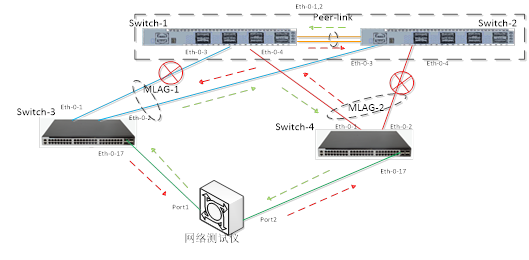
为了方便测试,这里用另一台交换机代替服务器,使用网络测试仪的两个测试端口模拟终端收发数据(为方便实验观察,switch-3和switch-4与switch-1和switch-2之间是1G链路,实际使用中推荐用高带宽端口作为连接核心交换机的上行链路)。
实际连接如下:

MLAG协议主要参数配置
首先,完成两台核心交换机完成MLAG协商所需要的配置:创建vlan,创建汇聚口,配置peer-link和peer-ip等。配置如下:
#################以下是switch-1的配置##################
Switch> enable
Switch# configure terminal
Enter configuration commands, one per line. End with CNTL/Z.
Switch(config)# vlan database
Switch(config-vlan)# vlan 4000
Switch(config-vlan)# exit
Switch(config)# interface range eth-0-1 – 2
Switch(config-if-range)# no shutdown
Switch(config-if-range)# switchport mode trunk
Switch(config-if-range)# switchport trunk allowed vlan add all
Switch(config-if-range)# static-channel-group 40
Switch(config-if-range)# exit
Switch(config)# interface vlan 4000
Switch(config-if)# ip addr 192.168.40.1/24
Switch(config-if)# exit
Switch(config)# interface agg 40
Switch(config-if)# spanning-tree port disable
Switch(config-if)# exit
Switch(config)# mlag configuration
Switch(config-mlag)# peer-link agg 40
Switch(config-mlag)# peer-address 192.168.40.2
Switch(config-mlag)# end
Switch#
#################以下是switch-2的配置##################
Switch# configure terminal
Enter configuration commands, one per line. End with CNTL/Z.
Switch(config)# vlan database
Switch(config-vlan)# vlan 4000
Switch(config-vlan)# exit
Switch(config)# interface range eth-0-1 – 2
Switch(config-if-range)# switchport mode trunk
Switch(config-if-range)# switchport trunk allowed vlan all
Switch(config-if-range)# static-channel-group 40
Switch(config-if-range)# exit
Switch(config)# interface vlan 4000
Switch(config-if)# ip address 192.168.40.2/24
Switch(config-if)# exit
Switch(config)# interface agg 40
Switch(config-if)# spanning-tree port disable
Switch(config-if)# exit
Switch(config)# mlag configuration
Switch(config-mlag)# peer-link agg 40
Switch(config-mlag)# peer-address 192.168.40.1
Switch(config-mlag)# end
Switch#
MLAG配置和协商检查
以上配置完成后可以检查两台交换机的mlag协商状态:
Switch-1的状态:
Switch# show mlag
MLAG configuration:
—————–
role : Master
local_sysid : 34a3.9501.2cb0
remote_sysid : 0000.1a11.1100
mlag_sysid : 34a3.9501.2cb0
local_syspri : 32768
remote_syspri: 32768
mlag_syspri : 32768
peer-link : agg40
peer conf : Yes
reload-delay : Auto(300s)
Switch#
Switch-2的状态:
Switch# show mlag
MLAG configuration:
—————–
role : Slave
local_sysid : 0000.1a11.1100
remote_sysid : 34a3.9501.2cb0
mlag_sysid : 34a3.9501.2cb0
local_syspri : 32768
remote_syspri: 32768
mlag_syspri : 32768
peer-link : agg40
peer conf : Yes
reload-delay : Auto(300s)
Switch#
MLAG组的创建
接下来配置两台交换机上的MLAG组,并把接口加入到对应的组中:
#################以下是switch-1的配置##################
Switch# configure terminal
Enter configuration commands, one per line. End with CNTL/Z.
Switch(config)# vlan database
Switch(config-vlan)# vlan 10
Switch(config-vlan)# exit
Switch(config)# interface eth-0-3
Switch(config-if)# switchport access vlan 10
Switch(config-if)# static-channel-group 10
Switch(config-if)# exit
Switch(config)# interface agg 10
Switch(config-if)# mlag 1
Switch(config)# interface eth-0-4
Switch(config-if)# switchport access vlan 10
Switch(config-if)# static-channel-group 20
Switch(config-if)# exit
Switch(config)# interface agg 20
Switch(config-if)# mlag 2
在switch-2上做以上相同的配置。
对端交换机的配置
第三步是配置与核心相连的接入交换机switch-3和switch-4,配置比较简单,将实际连接的物理端口聚合后加入到对应的vlan,需要特别注意,根据具体场景的业务流配置聚合端口的负载均衡策略,充分发挥双活系统的优势。
注意:在实际使用中,switch-3可能是一台多网卡的服务器,该服务器通过多个网口与核心交换机Switch-1和Switch-2连接时,需要在服务器上将对应的网口绑定成逻辑上的一个虚拟网口(不同操作系统上的网口绑定方式差别较大,这里不再举例)。
############Switch-3上的配置###############
Switch# configure terminal
Enter configuration commands, one per line. End with CNTL/Z.
Switch(config)# vlan database
Switch(config-vlan)# vlan 10
Switch(config-if-range)# exit
Switch(config)# port-channel 10 load-balance-mode round-robin
Switch(config)# interface range eth-0-1 – 2
Switch(config-if-range)# switchport access vlan 10
Switch(config-if-range)# static-channel-group 10
Switch(config-if-range)# exit
Switch(config)# interface eth-0-17
Switch(config-if)# switchport access vlan 10
Switch(config-if)# flowcontrol send on
Switch(config-if)# end
Switch#
############Switch-4上的配置###############
Switch# configure terminal
Enter configuration commands, one per line. End with CNTL/Z.
Switch(config)# vlan database
Switch(config-vlan)# vlan 10
Switch(config-if-range)# exit
Switch(config)# port-channel 20 load-balance-mode round-robin
Switch(config)# interface range eth-0-1 – 2
Switch(config-if-range)# switchport access vlan 10
Switch(config-if-range)# static-channel-group 20
Switch(config-if-range)# exit
Switch(config)# interface eth-0-17
Switch(config-if)# switchport access vlan 10
Switch(config-if)# flowcontrol send on
Switch(config-if)# end
Switch#
实验验证
在上述的配置中switch-3和switch-4都加入了一个10G端口eth-0-17到vlan10中,这两个10G端口与测试仪器的10G端口连接,两个测试端口各创建50条字节长度64的stream向对端发送。
第一步,检查正常情况下的数据转发是否正常。
确保以上配置中相关的所有链路连接正常,端口状态为up,测试仪开始发送数据流后看到统计如下图:
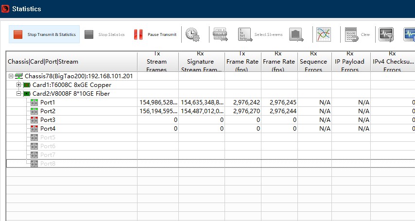
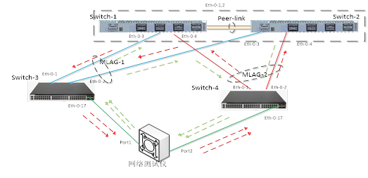
从测试仪两个接口的实时流量看传输带宽为2G,证明负载分担的预期目标达成。数据流转发情况如下图所示:
第二步,某条链路异常时的数据流转发是否符合预期
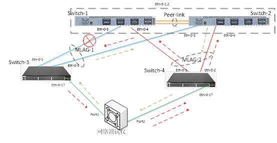
断掉其中一条链路,如下图:
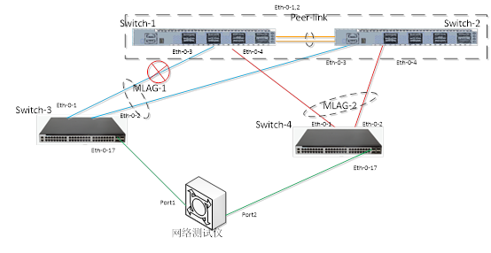
再看测试仪上的实时流量统计情况,数据转发没有中断,只是因为核心到switch-3之间仅有一条1G的链路可用,转发数据流量减少了一半:
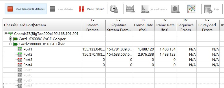
实际流量转发情况与预期一致,数据流情况如下图示:
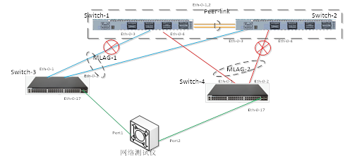
第三步,再断开一条链路,检查peer-link是否可以转发业务数据
继续断开switch-4和switch-2之间的连接,如下图:
再看测试仪上收发包情况:
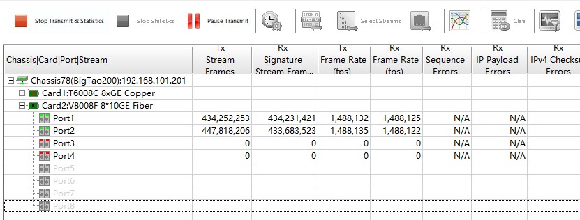
实际流量转发情况与预期一致,数据流情况如下图示:
